Telemetry
Telemetry allows you to know what is happening on your aircraft while you are flying it. Among other things you can receive battery voltages and GPS positions on your transmitter.
Telemetry can be either always on, or enabled when armed. If a serial port for telemetry is shared with other functionality then then telemetry will only be enabled when armed on that port.
Telemetry is enabled using the 'TELEMETRY` feature.
feature TELEMETRY
Multiple telemetry providers are currently supported, FrSky, Graupner HoTT V4, SmartPort (S.Port) and LightTelemetry (LTM)
All telemetry systems use serial ports, configure serial ports to use the telemetry system required.
FrSky telemetry
FrSky telemetry is transmit only and just requires a single connection from the TX pin of a serial port to the RX pin on an FrSky telemetry receiver.
FrSky telemetry signals are inverted. To connect a cleanflight capable board to an FrSKy receiver you have some options.
- A hardware inverter - Built in to some flight controllers.
- Use software serial and enable frsky_inversion.
- Use a flight controller that has software configurable hardware inversion (e.g. STM32F30x).
For 1, just connect your inverter to a usart or software serial port.
For 2 and 3 use the CLI command as follows:
set telemetry_inversion = ON
Available sensors
The following sensors are transmitted :
Vspd : vertical speed, unit is cm/s.
Hdg : heading, North is 0°, South is 180°.
AccX,Y,Z : accelerometers values.
Tmp1 : baro temp if available, gyro otherwise.
RPM : if armed : throttle value, battery capacity otherwise. (Blade number needs to be set to 12 in Taranis).
Cels : average cell value, vbat divided by cell number.
VFAS : actual vbat value (see VFAS precision section bellow).
Curr : actual current comsuption, in amp.
Fuel : if capacity set :remaining battery percentage, mah drawn otherwise.
GPS : GPS coordinates.
Alt : barometer based altitude, init level is zero.
Date : time since powered.
GSpd : current speed, calculated by GPS.
GAlt : GPS altitude, sea level is zero.
Tmp2 : number of sats. Every second, a number > 100 is sent to represent GPS signal quality.
Precision setting for VFAS
Cleanflight can send VFAS (FrSky Ampere Sensor Voltage) in two ways:
set frsky_vfas_precision = 0
This is default setting which supports VFAS resolution of 0.2 volts and is supported on all FrSky hardware.
set frsky_vfas_precision = 1
This is new setting which supports VFAS resolution of 0.1 volts and is only supported by OpenTX radios (this method uses custom ID 0x39).
HoTT telemetry
Only Electric Air Modules and GPS Modules are emulated.
Use the latest Graupner firmware for your transmitter and receiver.
Older HoTT transmitters required the EAM and GPS modules to be enabled in the telemetry menu of the transmitter. (e.g. on MX-20)
Serial ports use two wires but HoTT uses a single wire so some electronics are required so that the signals don't get mixed up. The TX and RX pins of
a serial port should be connected using a diode and a single wire to the T port on a HoTT receiver.
Connect as follows:
- HoTT TX/RX
T-> Serial RX (connect directly) - HoTT TX/RX
T-> Diode-( |)-> Serial TX (connect via diode)
The diode should be arranged to allow the data signals to flow the right way
-( |)- == Diode, | indicates cathode marker.
1N4148 diodes have been tested and work with the GR-24.
As noticed by Skrebber the GR-12 (and probably GR-16/24, too) are based on a PIC 24FJ64GA-002, which has 5V tolerant digital pins.
Note: The SoftSerial ports may not be 5V tolerant on your board. Verify if you require a 5v/3.3v level shifters.
LightTelemetry (LTM)
LTM is a lightweight streaming telemetry protocol supported by a number of OSDs, ground stations and antenna trackers.
The Cleanflight implementation of LTM implements the following frames:
- G-FRAME: GPS information (lat, long, ground speed, altitude, sat info)
- A-FRAME: Attitude (pitch, roll, heading)
- S-FRAME: Status (voltage, current+, RSSI, airspeed+, status). Item suffixed '+' not implemented in Cleanflight.
- O-FRAME: Origin (home position, lat, long, altitude, fix)
In addition, in the inav (navigation-rewrite) fork: * N-FRAME: Navigation information (GPS mode, Nav mode, Nav action, Waypoint number, Nav Error, Nav Flags).
LTM is transmit only, and can work at any supported baud rate. It is designed to operate over 2400 baud (9600 in Cleanflight) and does not benefit from higher rates. It is thus usable on soft serial.
More information about the fields, encoding and enumerations may be found at https://github.com/stronnag/mwptools/blob/master/docs/ltm-definition.txt
SmartPort (S.Port)
Smartport is a telemetry system used by newer FrSky transmitters and receivers such as the Taranis/XJR and X8R, X6R and X4R(SB).
More information about the implementation can be found here: https://github.com/frank26080115/cleanflight/wiki/Using-Smart-Port
Available sensors
The following sensors are transmitted :
Alt : barometer based altitude, init level is zero.
Vspd : vertical speed, unit is cm/s.
Hdg : heading, North is 0°, South is 180°.
AccX,Y,Z : accelerometers values.
Tmp1 : actual flight mode, sent as 4 digits. Number is sent as (1)1234. Please ignore the leading 1, it is just there to ensure the number as always 5 digits (the 1 + 4 digits of actual data) the numbers are aditives (for example, if first digit after the leading 1 is 6, it means GPS Home and Headfree are both active) :
- 1 is GPS Hold, 2 is GPS Home, 4 is Headfree
- 1 is mag enabled, 2 is baro enabled, 4 is sonar enabled
- 1 is angle, 2 is horizon, 4 is passthrough
- 1 is ok to arm, 2 is arming is prevented, 4 is armed
Tmp2 : GPS lock status, Number is sent as 1234, the numbers are aditives :
- 1 is GPS Fix, 2 is GPS Home fix
- not used
- not used
- number of sats
VFAS : actual vbat value.
GAlt : GPS altitude, sea level is zero.
GSpd : current speed, calculated by GPS.
GPS : GPS coordinates.
Integrate Cleanflight telemetry with FrSky Smartport sensors
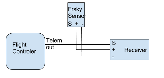
While Cleanflight telemetry brings a lot of valuable data to the radio, there are additional sensors, like Lipo cells sensor FLVSS, that can be a great addition for many aircrafts. Smartport sensors are designed to be daisy chained, and CF telemetry is no exception to that. To add an external sensor, just connect the "S" port of the FC and sensor(s) together, and ensure the sensor(s) are getting connected to GND and VCC either from the controler or the receiver
SmartPort on F3 targets with hardware UART
Smartport devices can be connected directly to STM32F3 boards such as the SPRacingF3 and Sparky, with a single straight through cable without the need for any hardware modifications on the FC or the receiver. Connect the TX PIN of the UART to the Smartport signal pin.
For Smartport on F3 based boards, enable the telemetry inversion setting.
set telemetry_inversion = ON
SmartPort on F1 and F3 targets with SoftSerial
Since F1 targets like Naze32 or Flip32 are not equipped with hardware inverters, SoftSerial might be simpler to use.
- Enable SoftSerial
feature SOFTSERIAL - In Configurator assign Telemetry > Smartport > Auto to SoftSerial port of your choice
- Enable Telemetry
feature TELEMETRY - Confirm telemetry invesion
set telemetry_inversion = ON - You have to bridge TX and RX lines of SoftSerial and connect them together to S.Port signal line in receiver
Notes:
- This has been tested with Flip32 and SPracingF3 boards and FrSky X8R and X4R receivers
- To discover all sensors board has to be armed, and when GPS is connected, it needs to have a proper 3D fix. When not armed, values like Vfas or GPS coordinates may not sent.